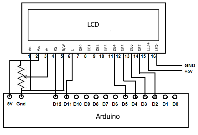

Contrast adjustment (VO) from potentiometer.The enable pin will be toggled to write data to the registers. The read/write pin will be pulled low (write only) as we only want to write to the LCD based on this setup. When toggled the other way (1) the register select pin goes into a data mode and will be used to send data to the screen. This is referred to as writing to the instruction or command register.

When pulled low it can send commands to the LCD (like position to move to, or clear the screen). We will only be using write mode and not reading any data. They are sending data to the display (toggled high/low). In this tutorial we will use 4 data pins (4-bit mode) and two control pins. The LCD uses a parallel interface meaning that we will need many pins from our raspberry pi to control it. These devices provide the same pinouts making them relatively easy to work with. You will find out if you don't get a row of blocks when you hook up power (pins 1, 2, and 3).Whenever you come across a LCD that looks like it has 16 connectors it is most likely using a HD44780 controller. Specifically, extended temperature range devices, like some of my Optrex modules, require a negative voltage on pin 3. Unfortunately the differences are in the letters following the the basic part number and those letters often deal with characteristics that may change the voltage required on pin3. Your datasheet link points to several similar LCD modules. If you run a later version of LiquidCrystal without that function the library will default to the setup for a one-line display (AARRGGHH). This means it was written for a LiquidCrystal library that predates v0017. Your tutorial is a bit outdated since it does not mention lcd.begin(). Many LCD modules, including many of the Optrex displays that I use, work satisfactorily with this pin grounded although they work better with a slight positive voltage.


This is the pin that should be driven by the wiper of the potentiometer. Pin 3 is almost always the power for the LCD display itself (as opposed to pin 2 which is the power for the LCD controller). Is this correct? If so, what do I do with the pin? Ground it? On the datasheet is lists pin 3 as "VEE", while in the tutorial I'm using it is listed as "V0", which is the variable operating leg of the pot for the backlight (I think). The Hitachi LCD interface upon which all else is based uses only 14 pins. Actually it's the other displays that have two extra pins (for the backlight). I'm guessing the missing 2 pins are for a backlight, which mine lacks.


 0 kommentar(er)
